Colin's Radio Control

Follow on Facebook Follow on X Follow on Youtube Follow on Thingiverse Follow on Creality Cloud Chat on Discord

Advanced Search
  • Plan database
  • GPS
    • .3gpl to .kml converter
    • NMEA to .kml converter
  • Calculators
    • Weight converter
    • Multicalc
  • Manuals
    • Aeroplanes
    • Transmitters
    • Receivers
    • VTx
    • Other Electronics
    • Other
    • Action cameras
    • Batteries & Chargers
    • Coverings
    • Drones
    • Engines & Motors
    • ESCs
    • Flight Controllers
    • FPV cameras
    • FPV Goggles
    • GPS
    • Helicopters
  • FlyBack
  • Aeroplanes
    • Balsa
      • Eclipse
      • Exp 1R
      • Katana MX
      • Piper J3 Cub
      • Weekend Wren
      • Wot 4
      • Wot 4 mini
      • Yak 54
    • Foamies
      • Bixler 2
      • Bixler 3
      • Catalina (foamie)
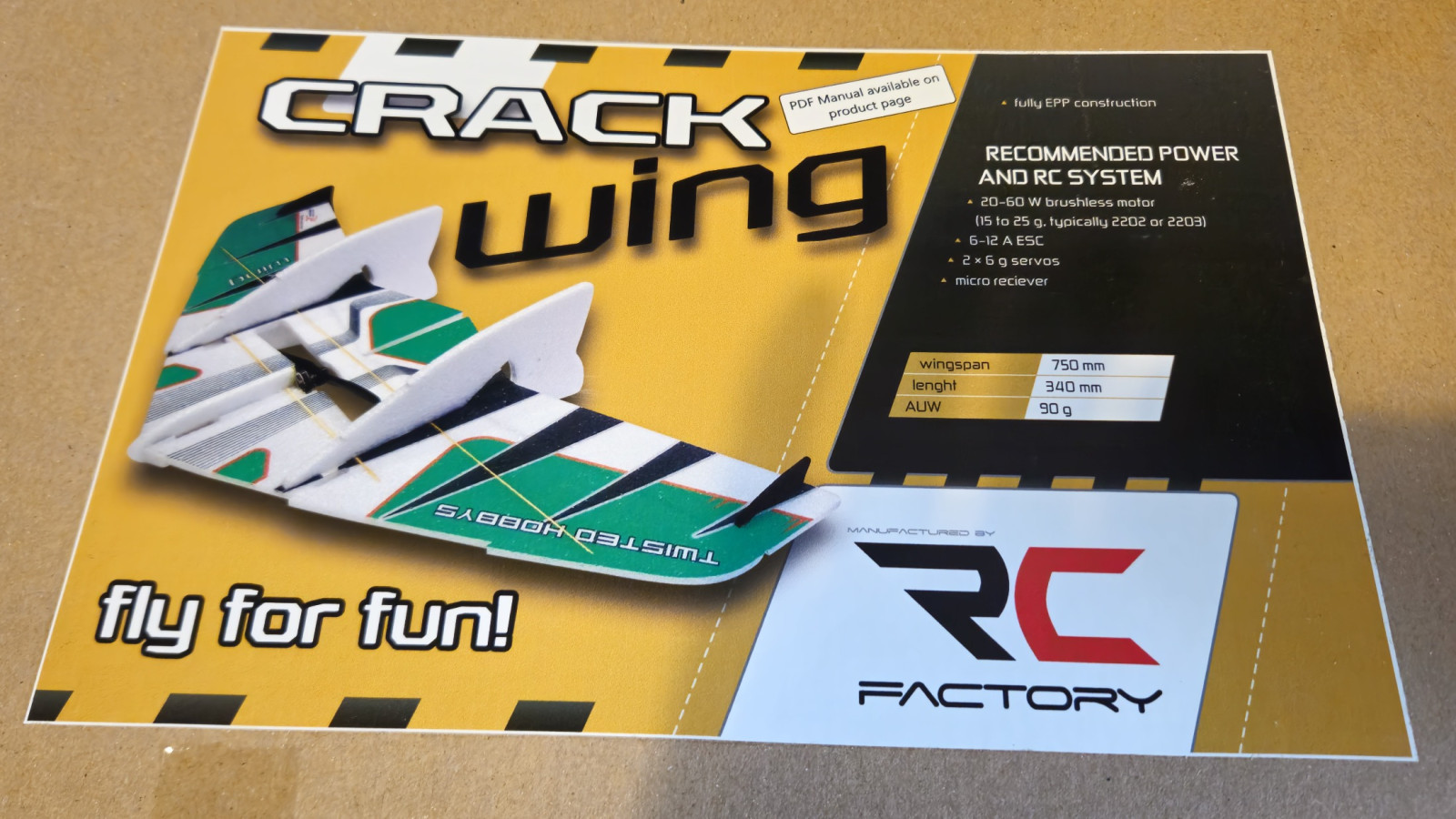
      • Crack wing
      • Durafly Tundra
      • Firefly
      • FX-61 Phantom
      • Hunter SU-27
      • Lidl Glider
      • Micro SU-27
      • Simples
      • T1 VTOL
      • UMX Slow Ultra Stick
      • UMX Ultrix
      • XBF 109
    • Carbon fibre
      • Mini Vapor
      • Night Vapor
    • BMFA
      • BMFA Dart
      • BMFA Rookie
      • Foamie glider
    • Projects
      • Catalina
      • Challenger
      • Clownfish
      • Mercury Matador
      • Printed wing
    • Retired
      • Crow
      • Cystalwing
      • Helium
  • Cars
    • Tamiya Frog
    • Tamiya Grasshopper
    • FCX24M Range Rover
    • Retired
      • Graupner Impuls Sport
      • Himoto Viper
      • GV Rex-X
      • Mini Racer
  • Multi-rotor
    • Air 65 II
    • Air 75
    • Aquila 20 HD
    • Bashful
    • Blinky
    • Cetus
    • Cetus Pro
    • Clyde
    • Dragonfly 3
    • Dragonfly 4
    • Mijia V666
    • Pokey
    • Sequre Bkli10
    • Shadow
    • Tunigy Micro X
    • Retired
      • Tricopter #1
      • Dragonfly
      • Dragonfly 2
      • Octopussy
      • Inky
      • Pinky
      • Orson
      • Test rig
      • Armor 85 HD
      • FQ777 Spider c126
      • Hummingbird
      • Walkera QR Y-100
  • Hovercraft
    • Vectorcraft
    • Vectorcraft XL
    • Retired
  • Helicopters
    • Goosky S1
    • Graupner HeliMax 40
    • Gyroo
    • Mini Heli
    • Retired
      • MicroMold Lark 2
  1. You are here:  
  2. Home
  3. Gallery
  4. Aeroplanes
  5. Crack wing

Navigation

  • Home
  • Gallery
  • Web links
  • Manufacturers
  • Classified ads
  • About me
  • Login

Downloads

  • BLHeli_32 music
  • LUA scripts
  • CAD
  • Build packs

Tools & machines

  • Laser cutter
  • 3D Printer

Components

  • Engines & motors
  • Electronics
  • Radio
  • Building materials
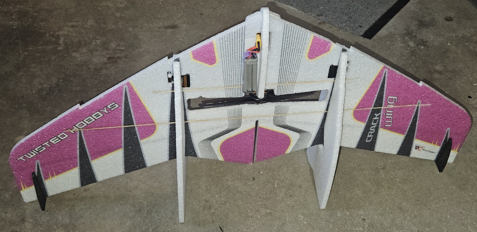
  • Ready for takeoff.

    crack wing crack wing
    crack wing
  • Completed model.

    crack wing crack wing
    crack wing
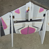
  • Top of the model. The battery is held in place with velcro.

    crack wing crack wing
    crack wing
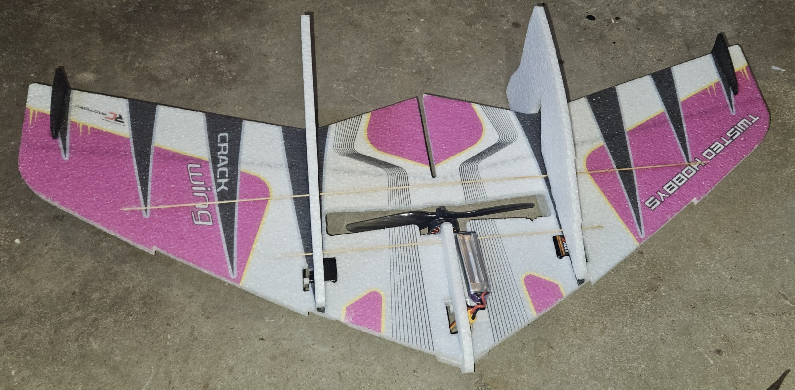
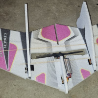
  • Underside of the model.

    crack wing crack wing
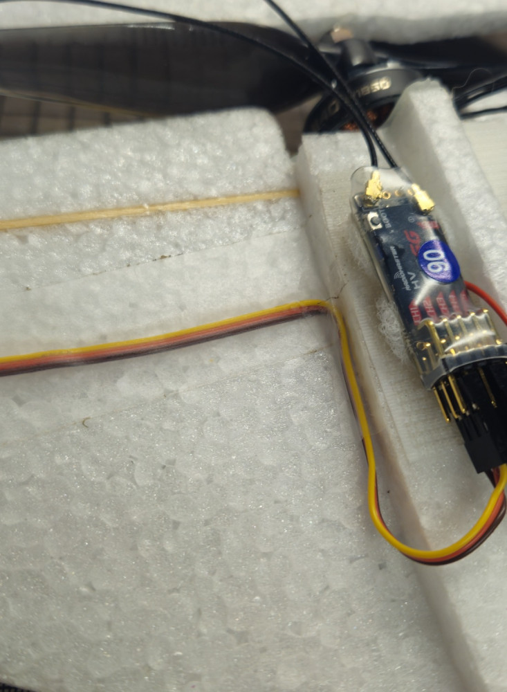
    crack wing
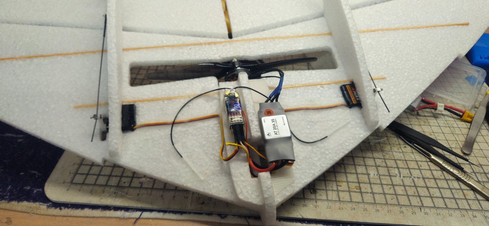
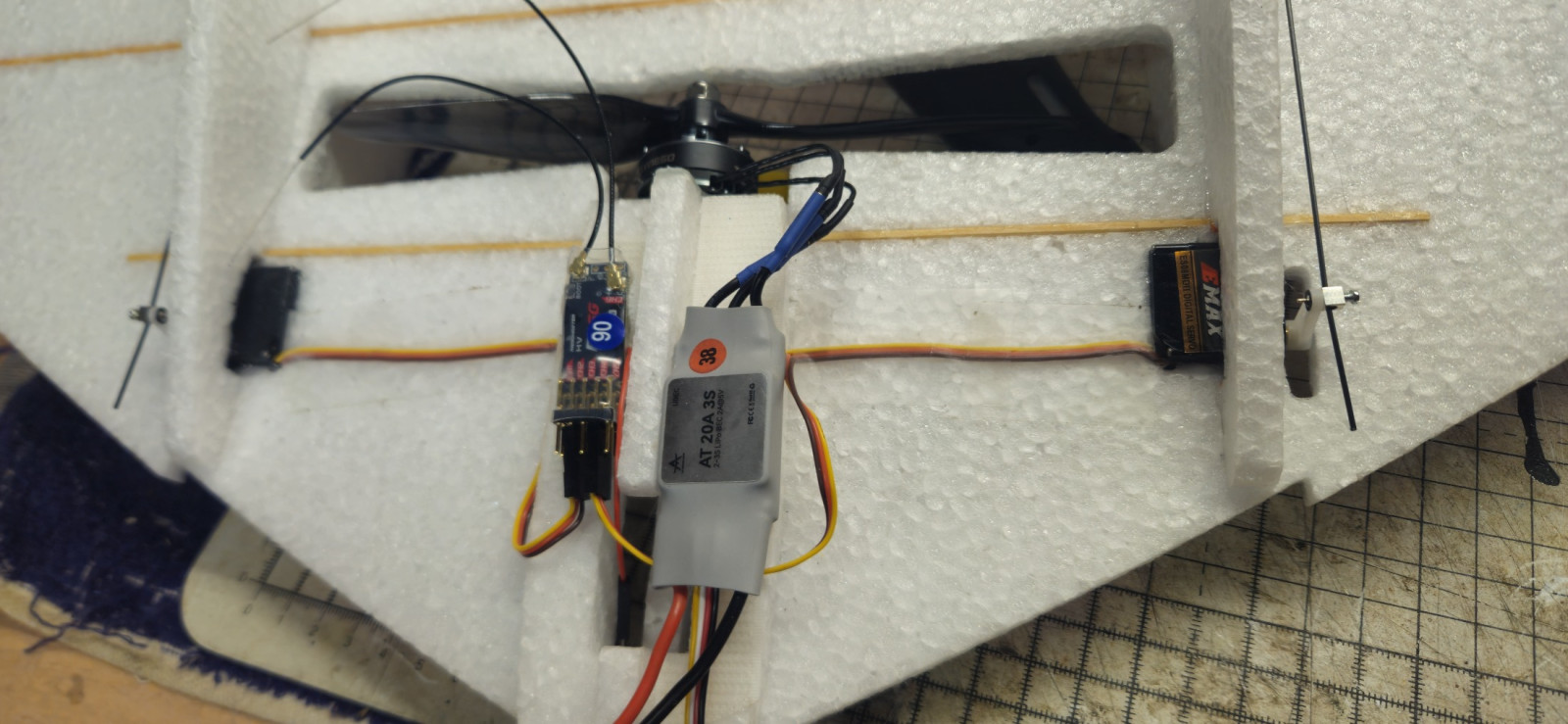
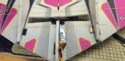
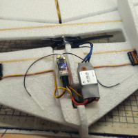
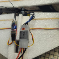
  • The Receiver and ESC are held in place with velcro.

    crack wing crack wing
    crack wing
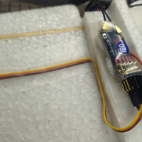
  • Tape the servo wires to the wing to keep them neat. I use Blenderm tape.

    crack wing crack wing
    crack wing
  • Glue the motor mount to the model.

    crack wing crack wing
    crack wing
  • Glue the motor mount to the model.

    crack wing crack wing
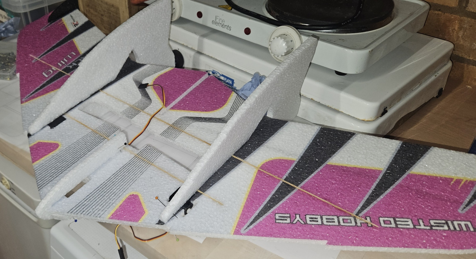
    crack wing
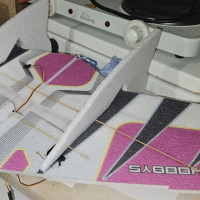
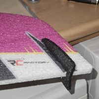
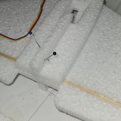
  • Pin the fin in place while the glue sets to ensure they are perpendicular to the wing.

    crack wing crack wing
    crack wing
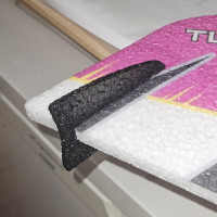
  • Fin glued in place snugly over the servo.

    crack wing crack wing
    crack wing
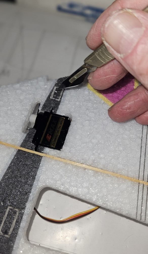
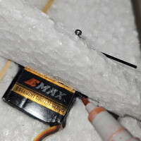
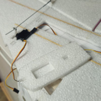
  • If your servos are thicker than the wing, you will need to cut out part of the fins to accomodate them.

    crack wing crack wing
    crack wing
  • Tab 4

    crack wing crack wing
    crack wing
  • Tab 3

    crack wing crack wing
    crack wing
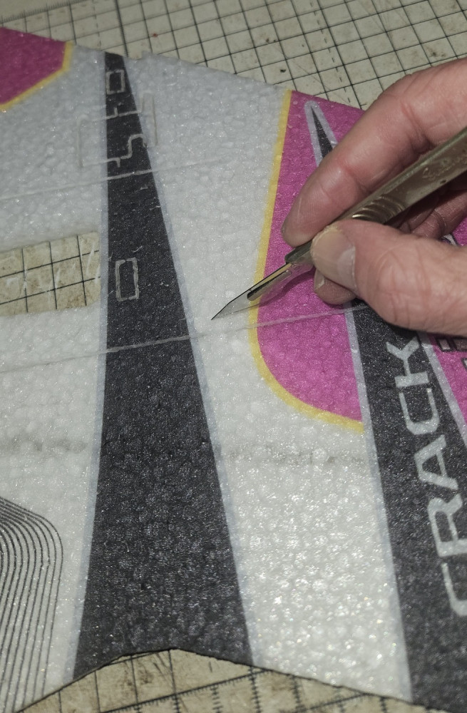
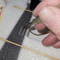
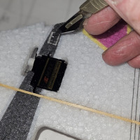
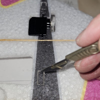
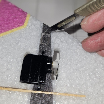
  • There are 4 tabs to cut out.

    crack wing crack wing
    crack wing
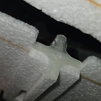
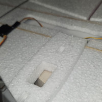
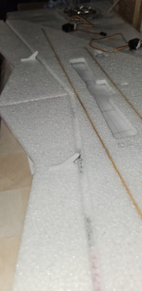
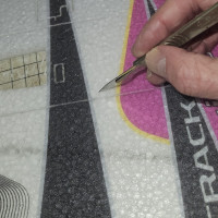
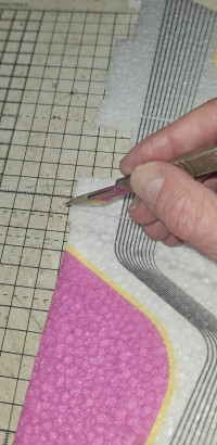
  • On the wing, cut out the tabs for the fins to insert into.

    crack wing crack wing
    crack wing
  • There's one in the centre and one at the end.

    crack wing crack wing
    crack wing
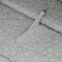
  • Cut the white fins to enable attaching to the wing.

    crack wing crack wing
    crack wing
  • Fin glued in place.

    crack wing crack wing
    crack wing
  • Fin glued in place.

    crack wing crack wing
    crack wing
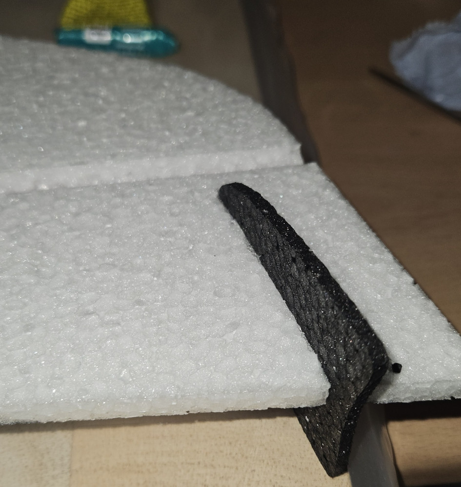
  • Glue the fin into the pre-cut slot.

    crack wing crack wing
    crack wing
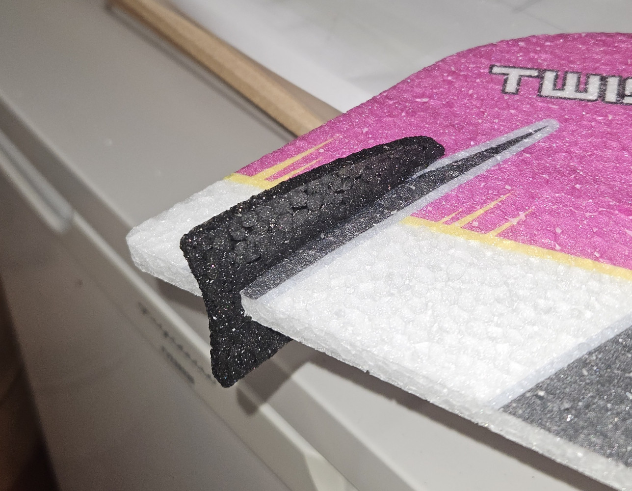
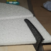
  • Fin held apart to demonstrate the cut (There shouldn't be a gap).

    crack wing crack wing
    crack wing
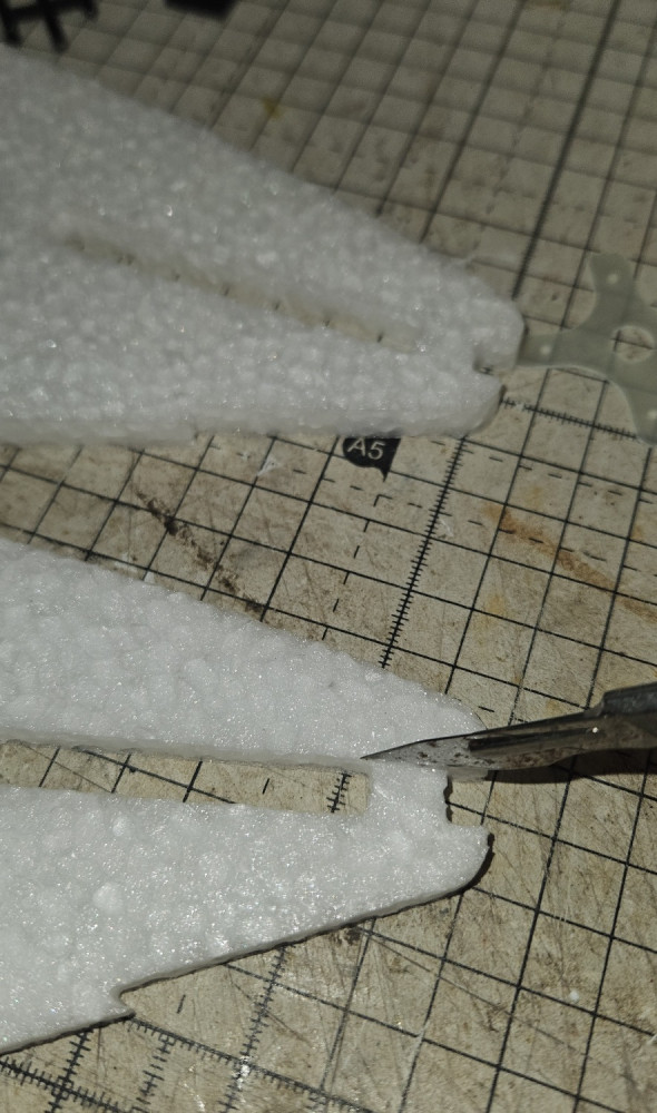
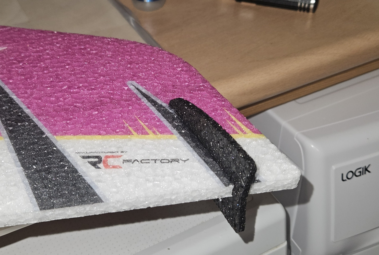
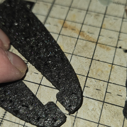
  • Cut the front of each of the black fins to enable them to be inserted in the elevons (they will be glued back together later)

    crack wing crack wing
    crack wing
  • Top part held with pins while the glue sets.

    crack wing crack wing
    crack wing
  • Make sure everything is lined up and secure with pins while the glue sets.

    crack wing crack wing
    crack wing
  • The top part glues in place. This also forms part of the motor mount.

    crack wing crack wing
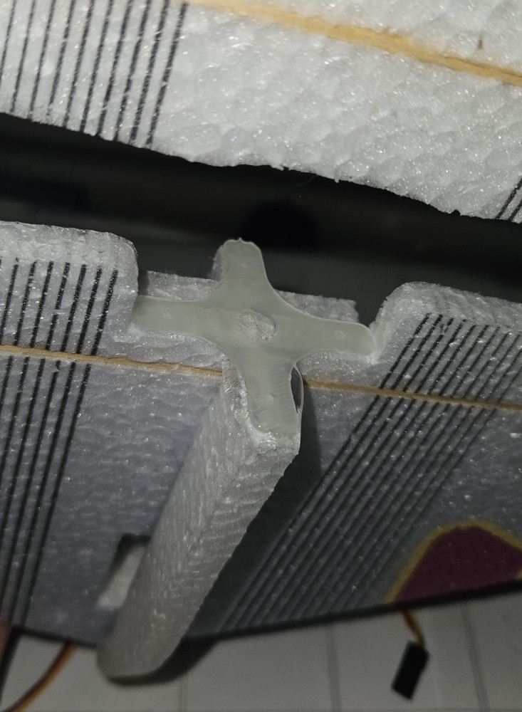
    crack wing
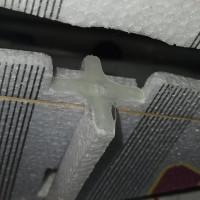
  • T shaped part glued in place.

    crack wing crack wing
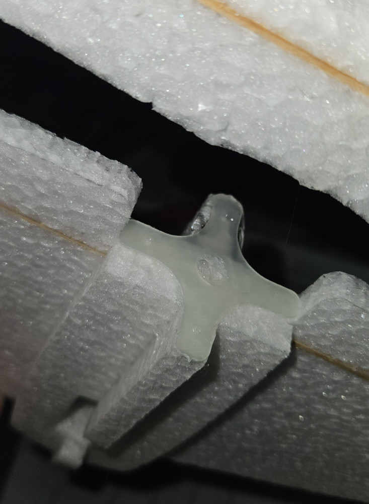
    crack wing
  • The T shaped part glues into the doubler. This forms part of the motor mount.

    crack wing crack wing
    crack wing
  • Front doubler glued in place.

    crack wing crack wing
    crack wing
  • Front doubler glued in place.

    crack wing crack wing
    crack wing
  • The front doubler goes on the underside of the wing.

    crack wing crack wing
    crack wing
  • Tighen the linkage

    crack wing crack wing
    crack wing
  • Tighten the linkage.

    crack wing crack wing
    crack wing
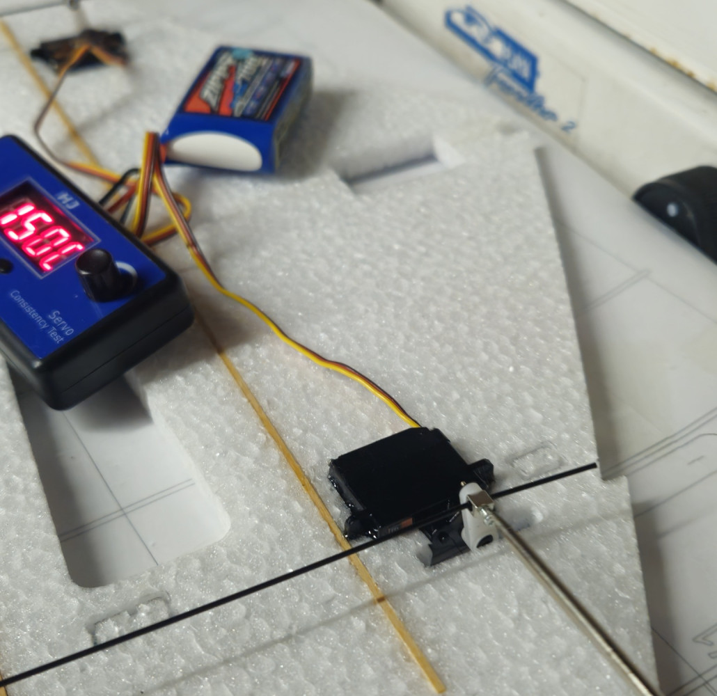
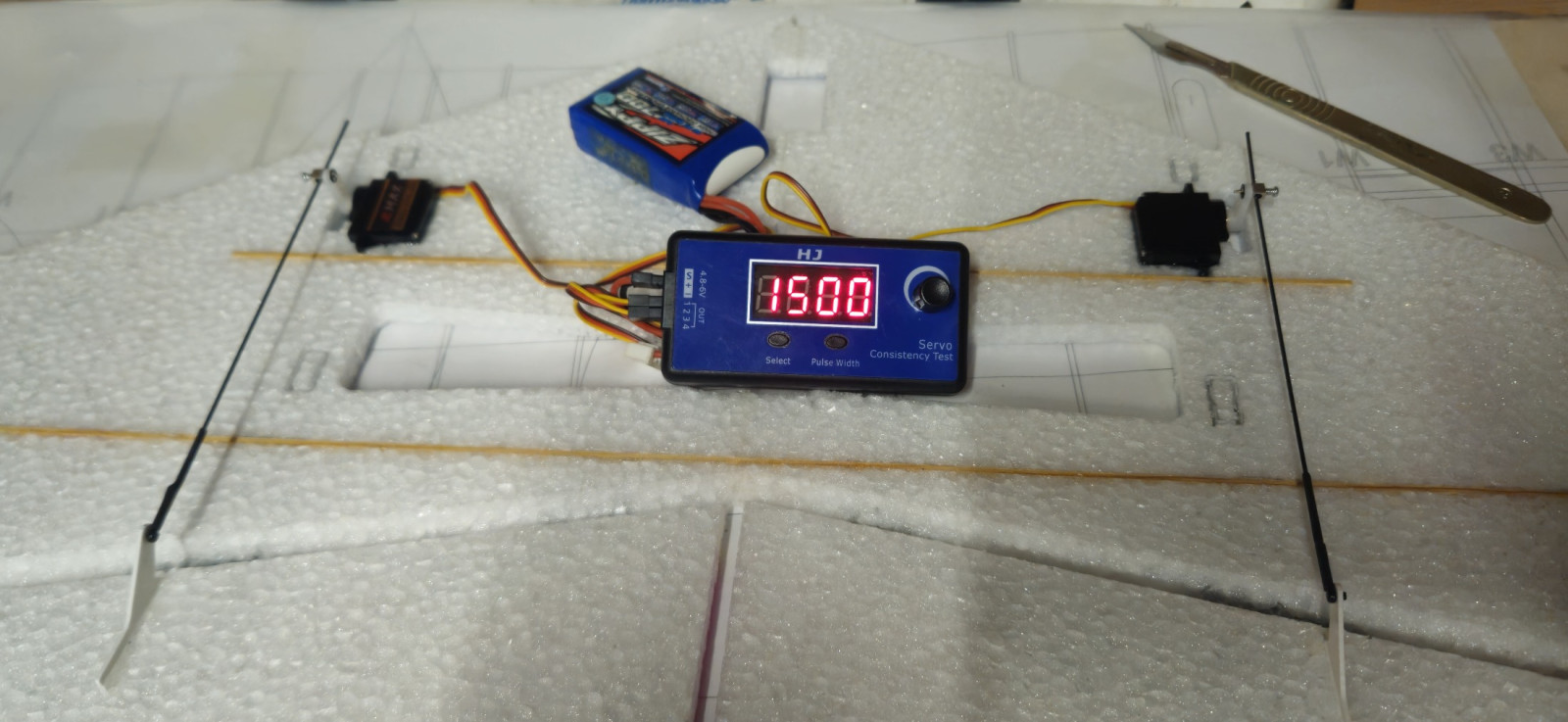
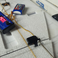
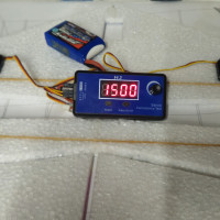
  • Centre the servos before tightening the linkages.

    crack wing crack wing
    crack wing
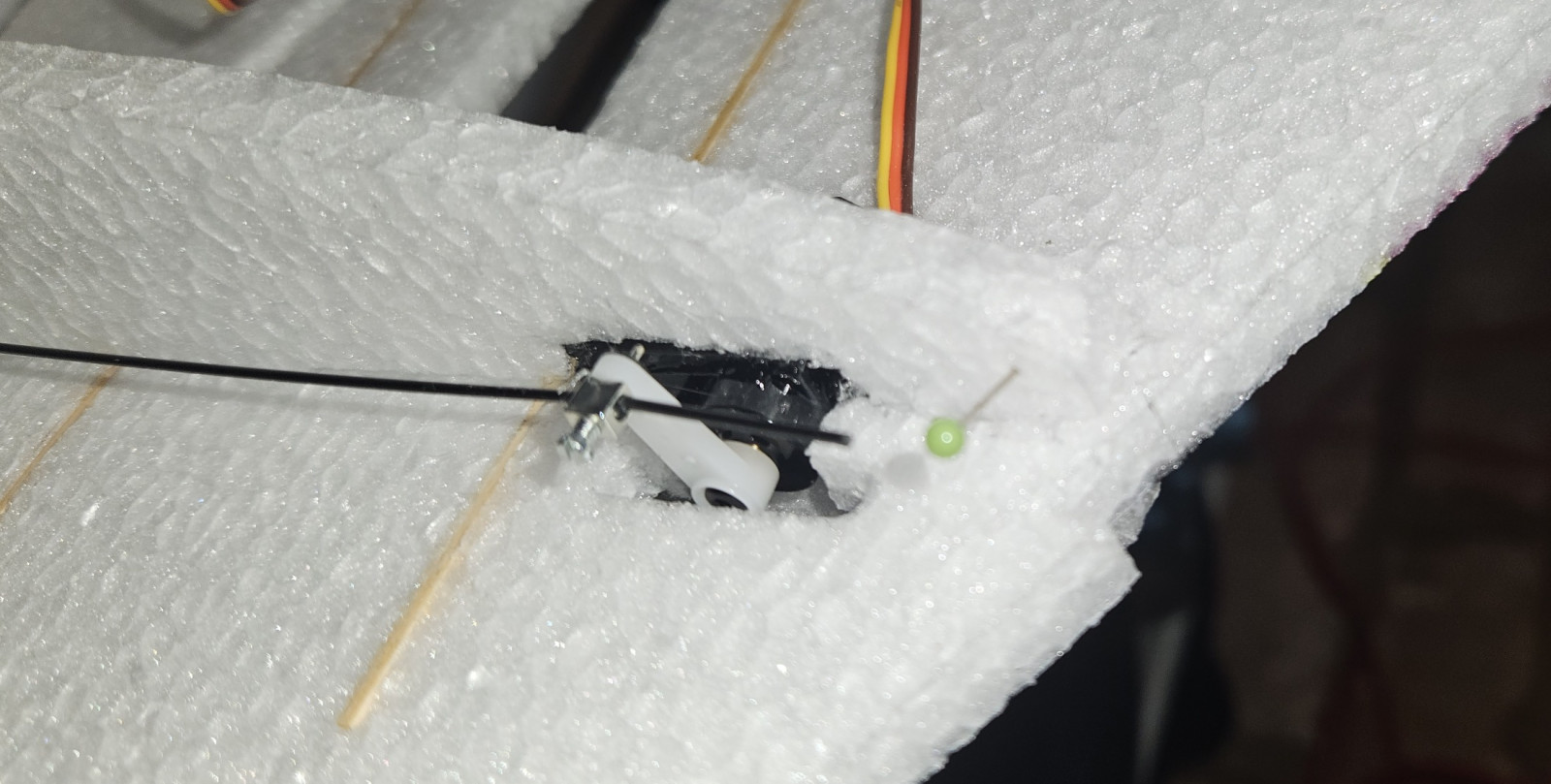
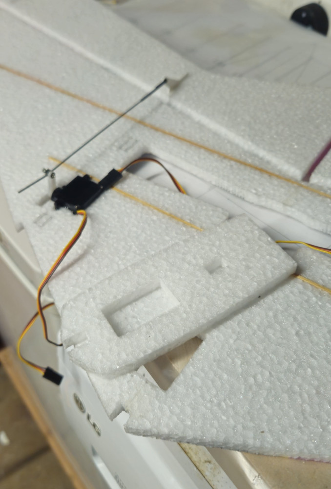
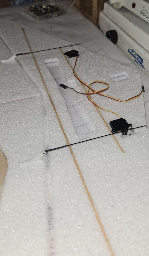
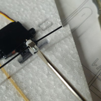
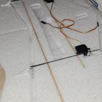
  • Servos and control linkages.

    crack wing crack wing
    crack wing
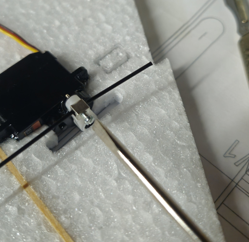
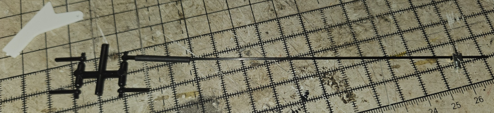
  • Make sure that the carbon rod and control rod end are side by side.

    crack wing crack wing
    crack wing
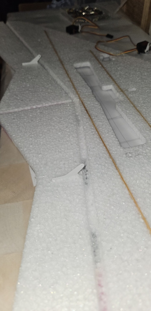
  • Both control horns glued in pleace.

    crack wing crack wing
    crack wing
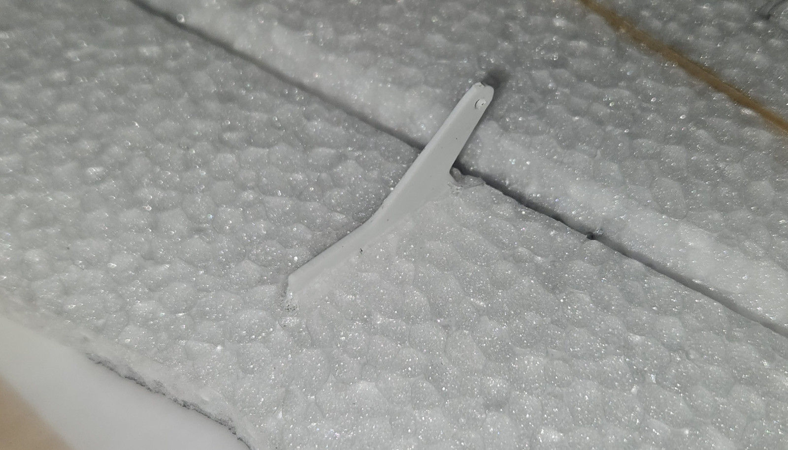
  • Control horn glued into the pre-cut slot on the underside of the elevon.

    crack wing crack wing
    crack wing
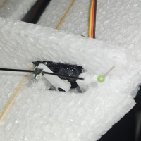
  • The linkages attached to the servo horn. They are held in place with starlock washers. Again, I had to enlarge the servo horn hole to 1.5mm.

    crack wing crack wing
    crack wing
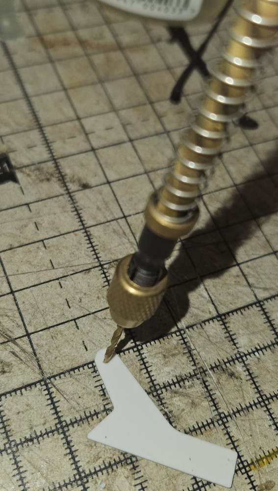
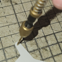
  • Drilling the other control horn.

    crack wing crack wing
    crack wing
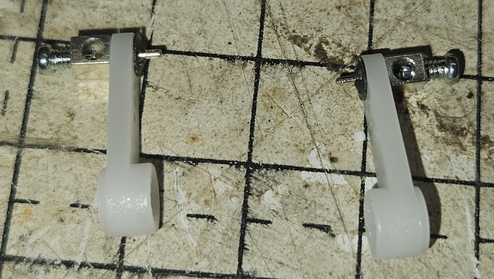
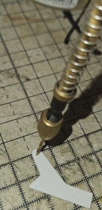
  • I found that I had to enlarge the hole in the control horn to 1.5mm. The control rod end then pressed in perfectly.

    crack wing crack wing
    crack wing
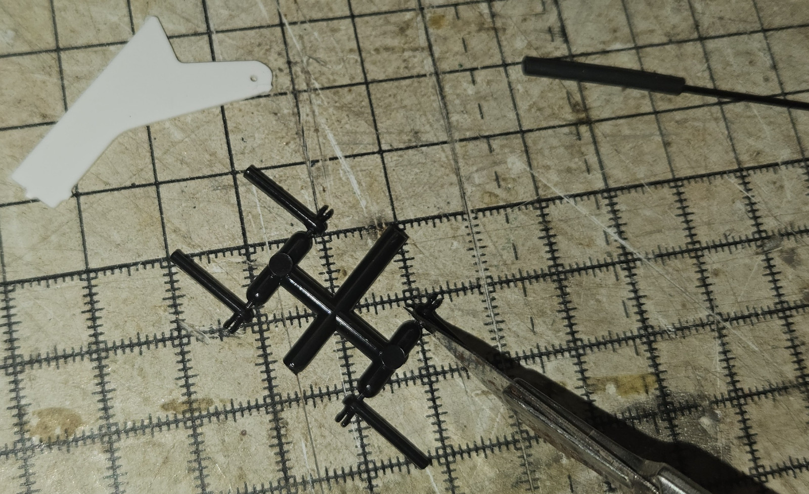
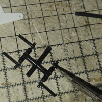
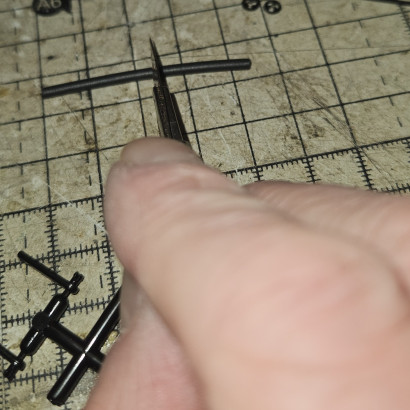
  • Cut the control rod end off the shipping frame.

    crack wing crack wing
    crack wing
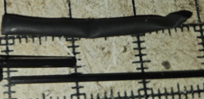
  • Insert the carbon rod and control rod end into the heatshrink. Ensure that the carbon rod and control rod end are side by side. If they are end to end, the linkage will bend.

    crack wing crack wing
    crack wing
  • Cut the heatshrink tube in two. You will need one piece for each of the elevon control rods.

    crack wing crack wing
    crack wing
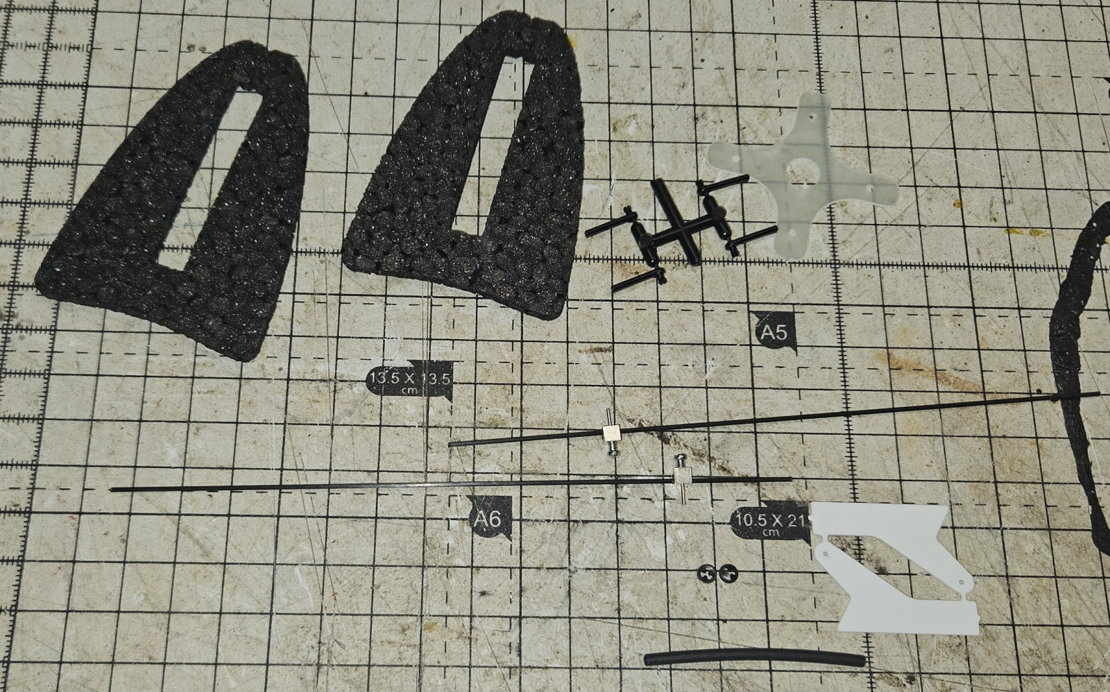
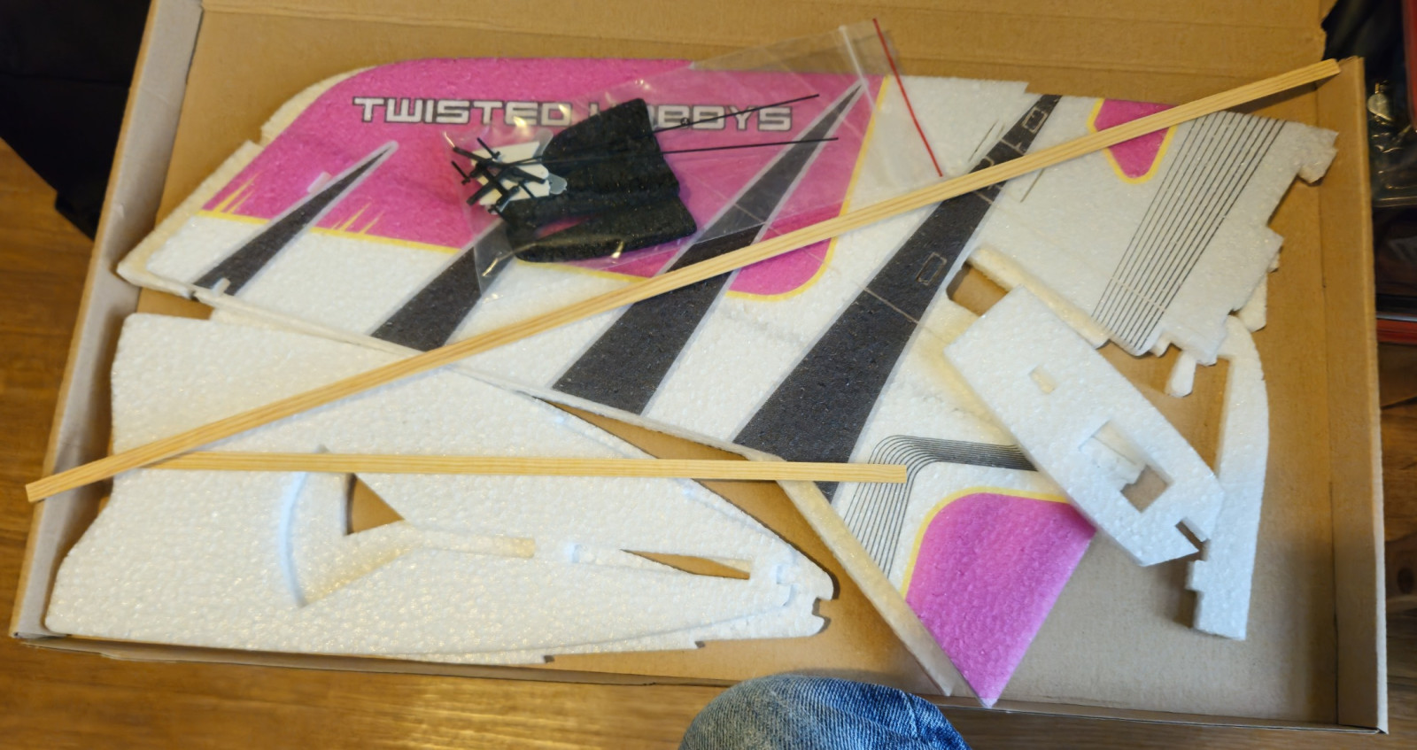
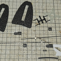
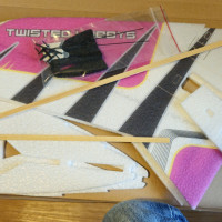
  • The small parts.

    crack wing crack wing
    crack wing
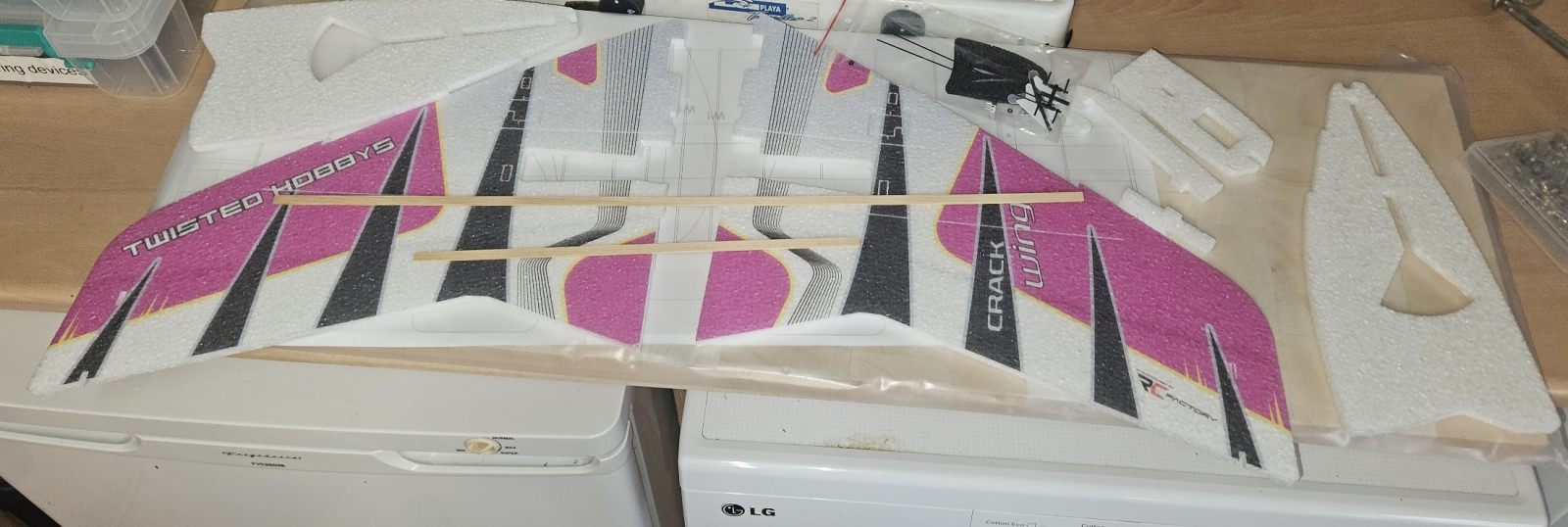
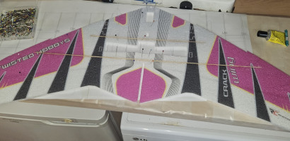
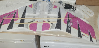
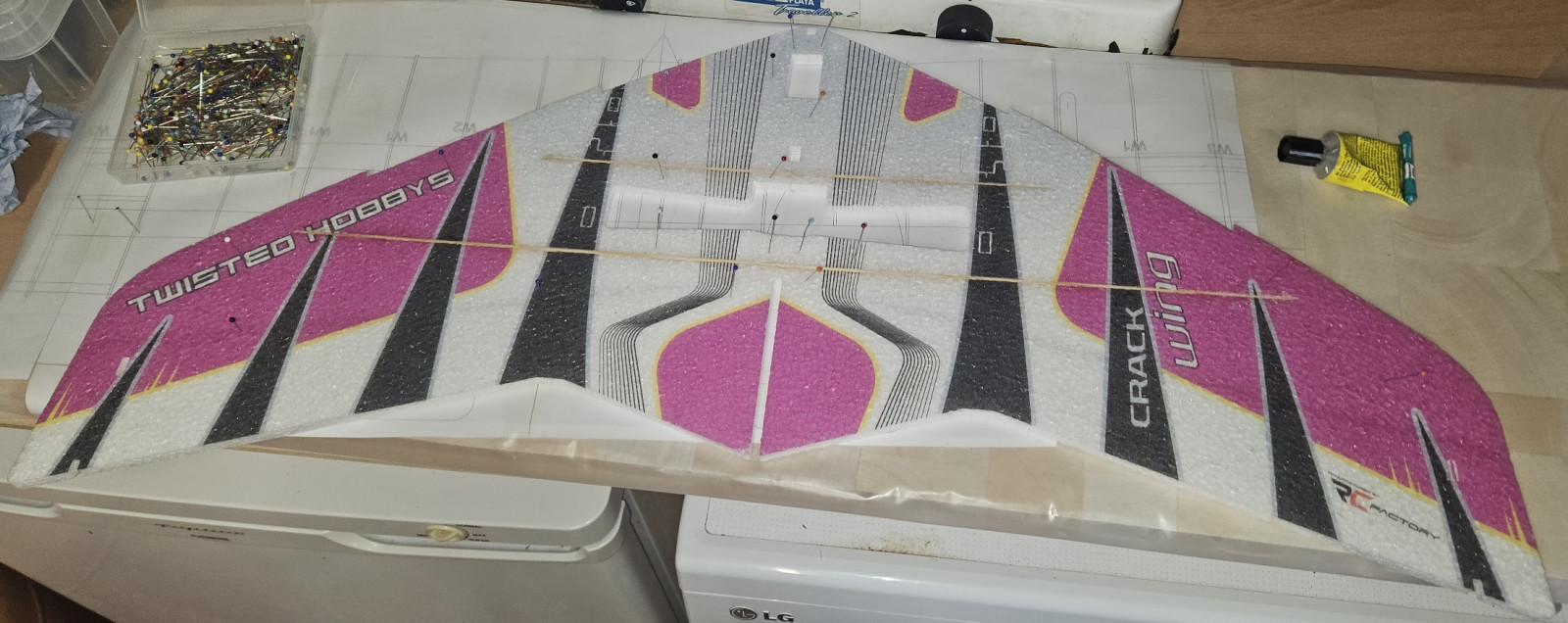
  • Pin the wing down to a build board, glue the wings together and glue in the spars.

    crack wing crack wing
    crack wing
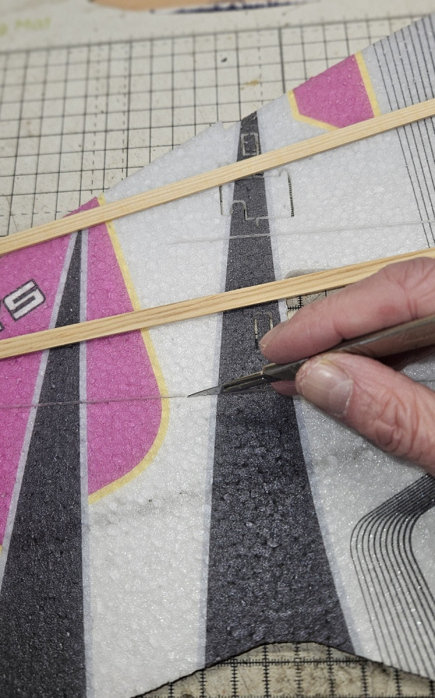
  • Yet more tabs.

    crack wing crack wing
    crack wing
  • And more tabs.

    crack wing crack wing
    crack wing
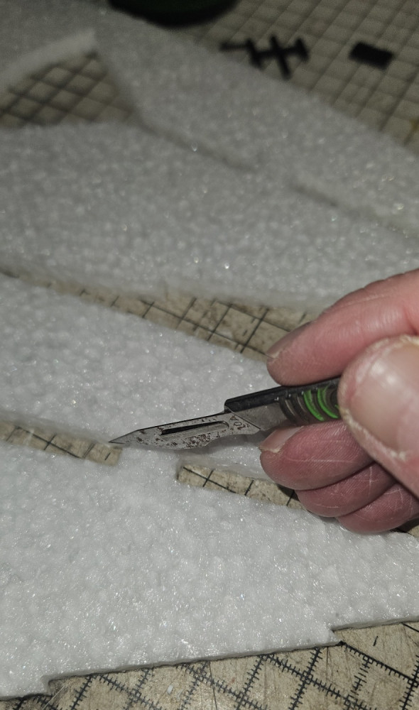
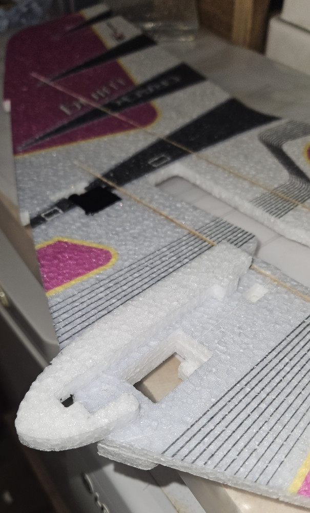
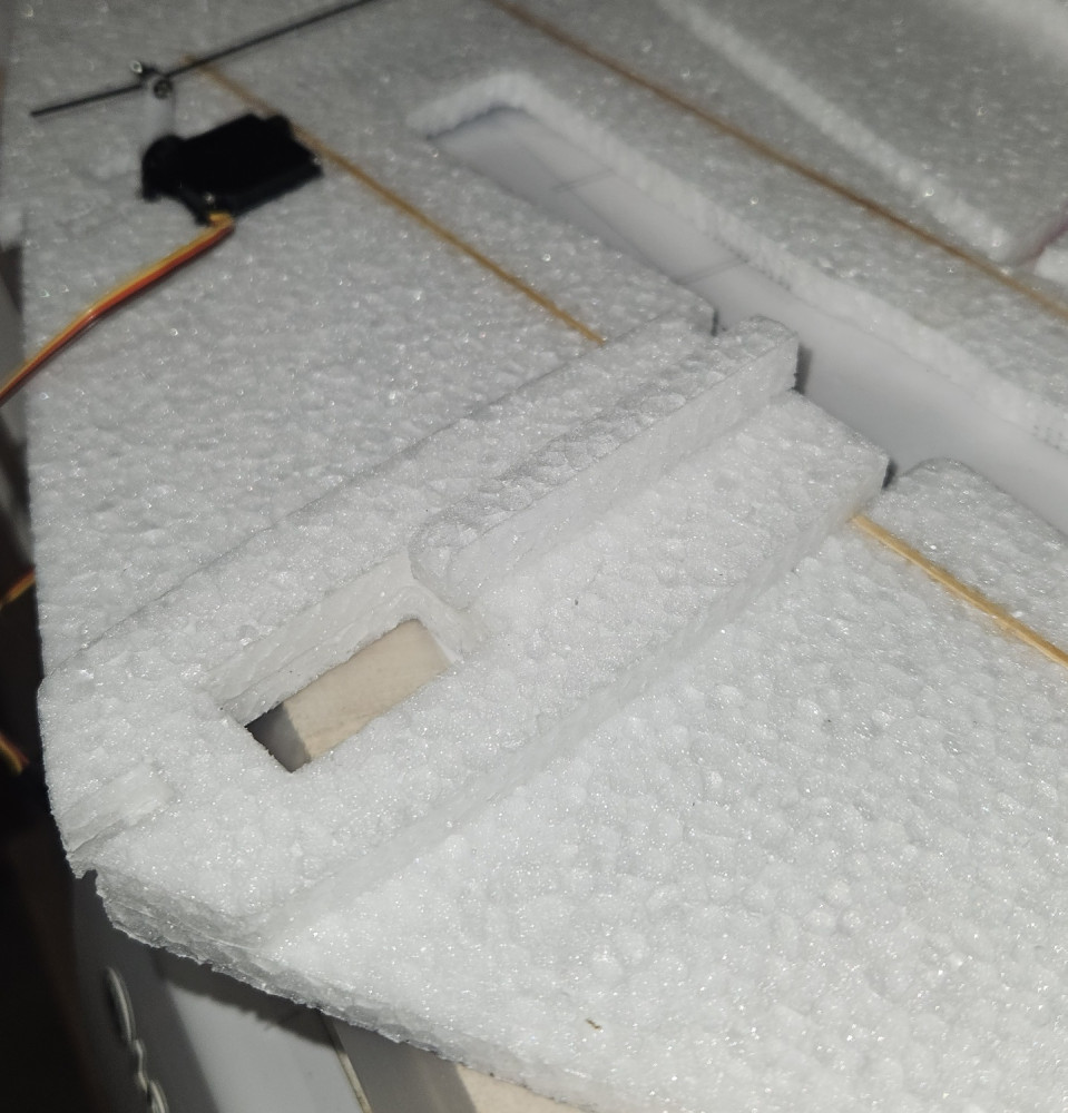
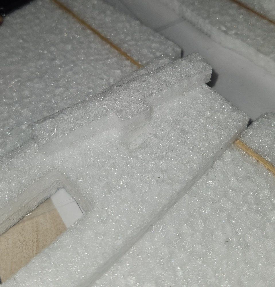
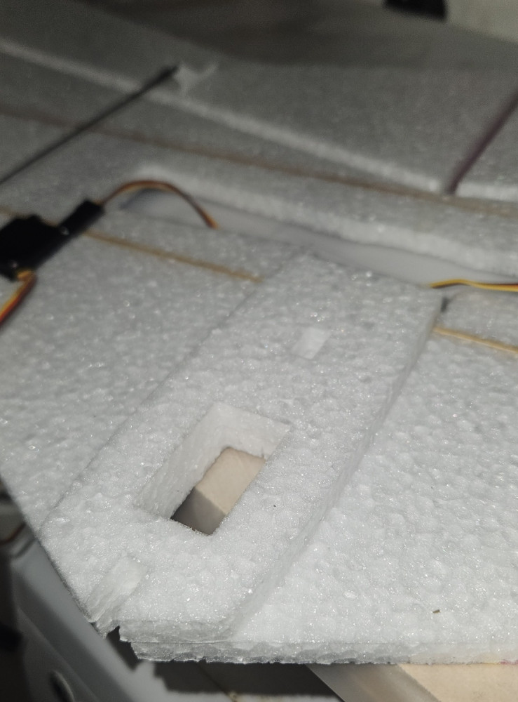
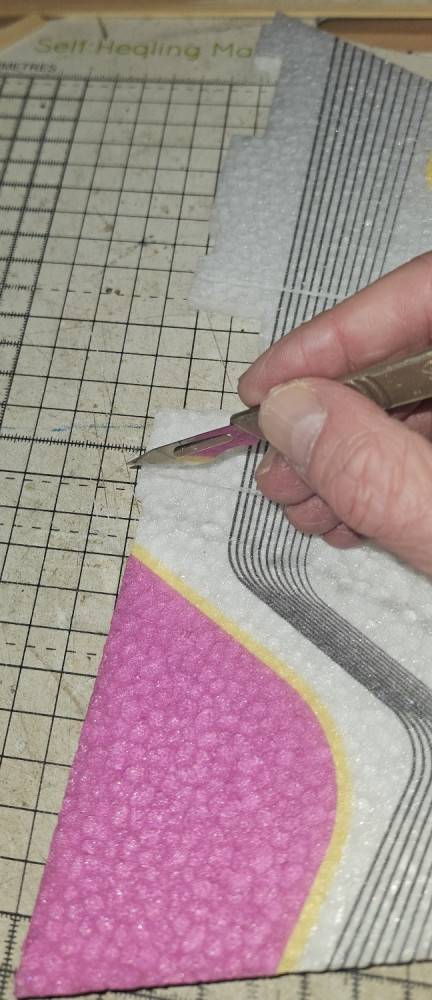
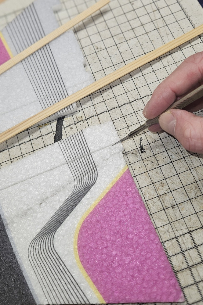
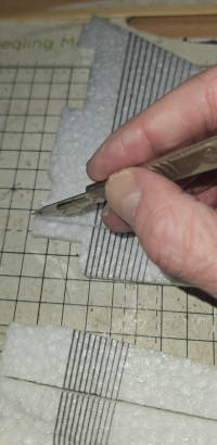
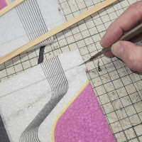
  • Cutting out the tabs on the other wing.

    crack wing crack wing
    crack wing
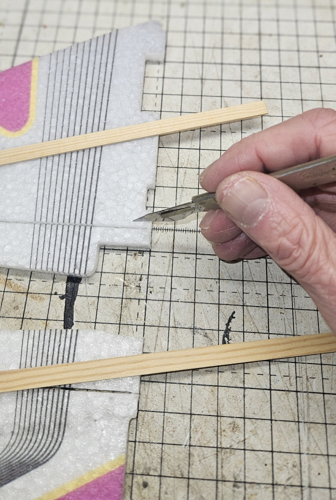
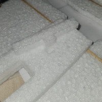
  • there are two tabs per slot per wing (8 in total).

    crack wing crack wing
    crack wing
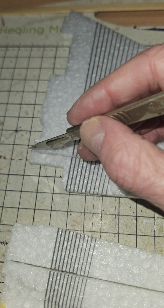
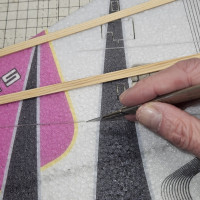
  • There's a tab around the centre of the slot in each wing and one at the end.

    crack wing crack wing
    crack wing
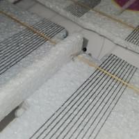
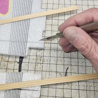
  • Cut out the tabs in the slots before glueing in the spars.

    crack wing crack wing
    crack wing
  • The two spars glue into pre-cut slots in the wing.

    crack wing crack wing
    crack wing
  • crack wing crack wing
    crack wing
  • crack wing crack wing
    crack wing
crack wing

Ready for takeoff.

crack wing

Completed model.

crack wing

Top of the model. The battery is held in place with velcro.

crack wing

Underside of the model.

crack wing

The Receiver and ESC are held in place with velcro.

crack wing

Tape the servo wires to the wing to keep them neat. I use Blenderm tape.

crack wing

Glue the motor mount to the model.

crack wing

Glue the motor mount to the model.

crack wing

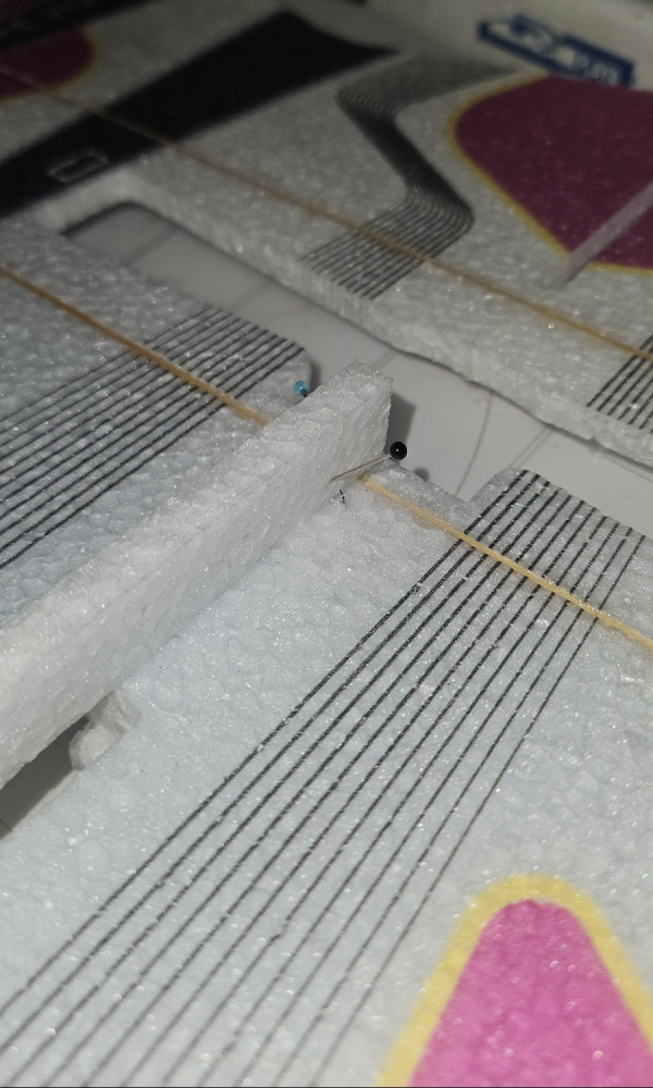
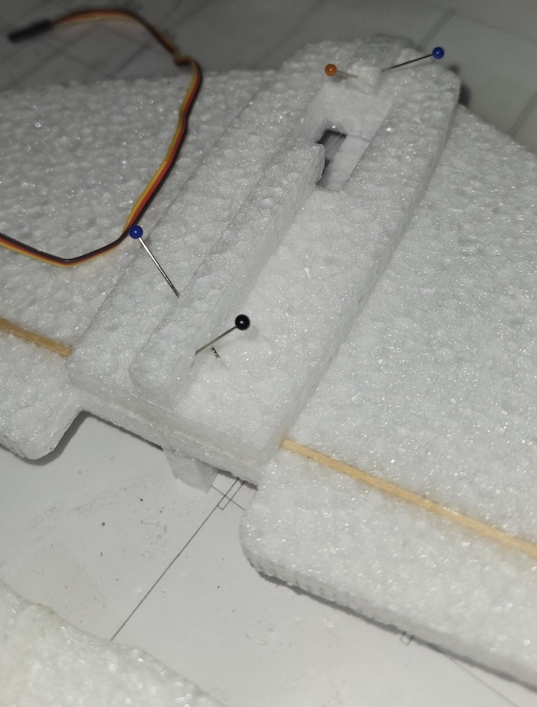
Pin the fin in place while the glue sets to ensure they are perpendicular to the wing.

crack wing

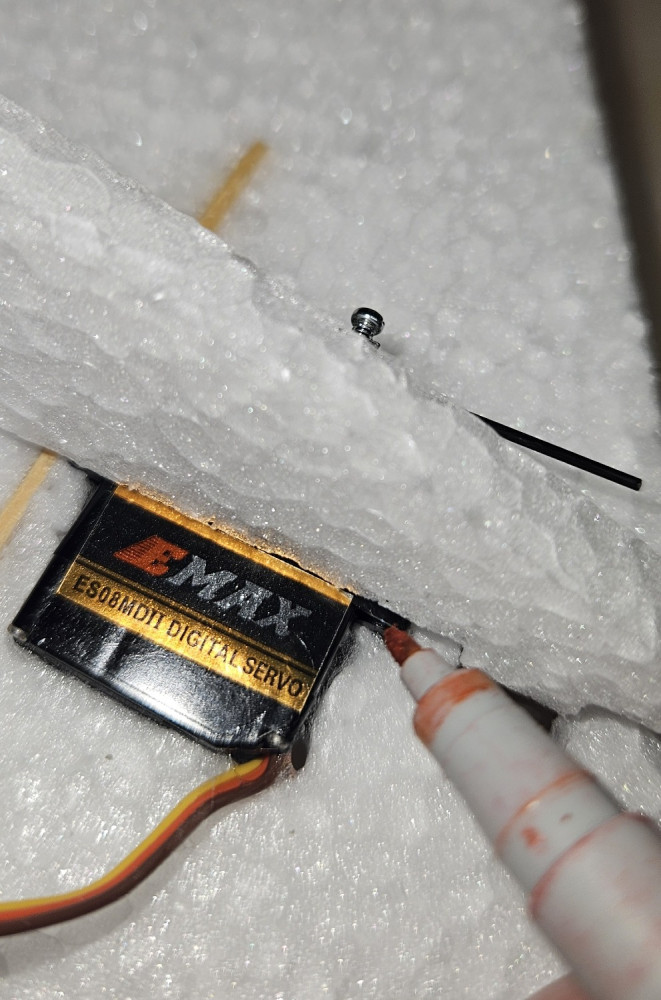
Fin glued in place snugly over the servo.

crack wing

If your servos are thicker than the wing, you will need to cut out part of the fins to accomodate them.

crack wing

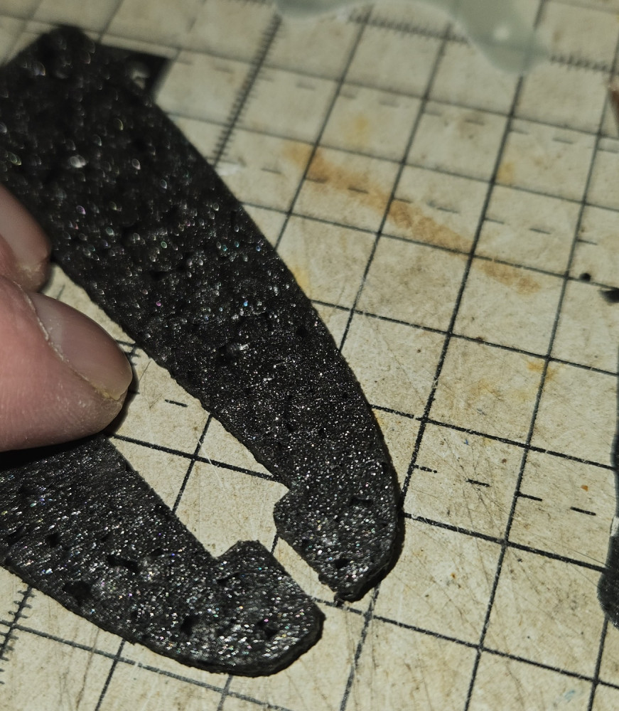
Tab 4

crack wing

Tab 3

crack wing

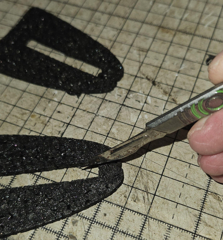
There are 4 tabs to cut out.

crack wing

On the wing, cut out the tabs for the fins to insert into.

crack wing

There's one in the centre and one at the end.

crack wing

Cut the white fins to enable attaching to the wing.

crack wing

Fin glued in place.

crack wing

Fin glued in place.

crack wing

Glue the fin into the pre-cut slot.

crack wing

Fin held apart to demonstrate the cut (There shouldn't be a gap).

crack wing

Cut the front of each of the black fins to enable them to be inserted in the elevons (they will be glued back together later)

crack wing

Top part held with pins while the glue sets.

crack wing

Make sure everything is lined up and secure with pins while the glue sets.

crack wing

The top part glues in place. This also forms part of the motor mount.

crack wing

T shaped part glued in place.

crack wing

The T shaped part glues into the doubler. This forms part of the motor mount.

crack wing

Front doubler glued in place.

crack wing

Front doubler glued in place.

crack wing

The front doubler goes on the underside of the wing.

crack wing

Tighen the linkage

crack wing

Tighten the linkage.

crack wing

Centre the servos before tightening the linkages.

crack wing

Servos and control linkages.

crack wing

Make sure that the carbon rod and control rod end are side by side.

crack wing

Both control horns glued in pleace.

crack wing

Control horn glued into the pre-cut slot on the underside of the elevon.

crack wing

The linkages attached to the servo horn. They are held in place with starlock washers. Again, I had to enlarge the servo horn hole to 1.5mm.

crack wing

Drilling the other control horn.

crack wing

I found that I had to enlarge the hole in the control horn to 1.5mm. The control rod end then pressed in perfectly.

crack wing

Cut the control rod end off the shipping frame.

crack wing

Insert the carbon rod and control rod end into the heatshrink. Ensure that the carbon rod and control rod end are side by side. If they are end to end, the linkage will bend.

crack wing

Cut the heatshrink tube in two. You will need one piece for each of the elevon control rods.

crack wing

The small parts.

crack wing

Pin the wing down to a build board, glue the wings together and glue in the spars.

crack wing

Yet more tabs.

crack wing

And more tabs.

crack wing

Cutting out the tabs on the other wing.

crack wing

there are two tabs per slot per wing (8 in total).

crack wing

There's a tab around the centre of the slot in each wing and one at the end.

crack wing

Cut out the tabs in the slots before glueing in the spars.

crack wing

The two spars glue into pre-cut slots in the wing.

crack wing
crack wing
    Copyright © 2026 Colin's Radio Control. All Rights Reserved.
    Joomla! is Free Software released under the GNU General Public License.